Wednesday, March 12, 2014

Power Line Communication - Possible applications (Part III)

PLC has great possibilities for using the yet installed electric system, reducing the investment in the communication system implementation. It is a communication system with important applications in the Smart Grid - mainly in AMI systems. Among others, PLC is well implemented in Automotive Industry with different protocols - as it has been introduced in the blog: Customer Service Strategy
PLC is in investigation in Avionics technology; one example is taupe project. 


Figure 1_Example of Rolls Royce turbine in BerlinTechnikmuseum. PLC is in investigation in Avionics due to increasing of cable harness in aircraft, mainly for being replaced hydraulic and pneumatic systems by electric systems. By this way, changing aircraft voltage levels and control systems, increasing the complexity and wires number. PLC systems are being in investigation for reducing the wire harness._Source; Javier Sanchez Rios.


The use of power network gives issues to transmit data, due to the nature of the electric network performance at low frequency, in Europe at 50 Hz and in North America at 60 Hz. 
PLC must coexist with other communication systems - wireless, optical, etc.- operating in the same frequency band in HV, MV and LV. The attenuation to the signal depending upon the distance, the frequency selectivity, high-power impulsive noise presence, with the variation in space, frequency and time, the most important issues for communication achievement.
1_ In first term, it is necessary to think about the implementation of PLC solutions in Smart Cities, naturally, the most implementations in this IoT in the cities are based in wireless communication infrastructure. However for existing infrastructure, PLC can help for implementation of Smart Grids in subterranean infrastructure, where there is no wireless cover.
Furthermore, the application in control of street lighting (for controlling lumen by current control), where the infrastructure is yet installed and besides possibilities for cameras in this street electric infrastructure for traffic or security solutions.
2_ In indoor EV charger mode 1 - 250 V monophasic or 480 V triphasic AC power. 

PLC will help to contact in non wireless cover places - subterranean parking, etc., between the on-board to off-board vehicle systems  - following IEC 61851-1. Connecting the EV charger to the BMS (Battery Management System) and EMS (Energy Management System) by LIN, CAN-C, CAN-B or FlexRay bus. 
After that, the communication from EV Charger to the next electrical point on the ground, is transmitted by wireless communication to ISP (Internet Service Provider) by one router or modem.
3_For critical infrastructure, if the system is supplied by two different electric systems, if one of it is by subterranean line, in case of emergency, the system can supply the electricity and also communication, just in terms of the emergency cases.

To introduce in the complexity of PLC communication, the PLC signal must be transmitted close to the zero-crossing voltage signal, but not in the same zero-crossing of the voltage signal - due to interference for being electric power.


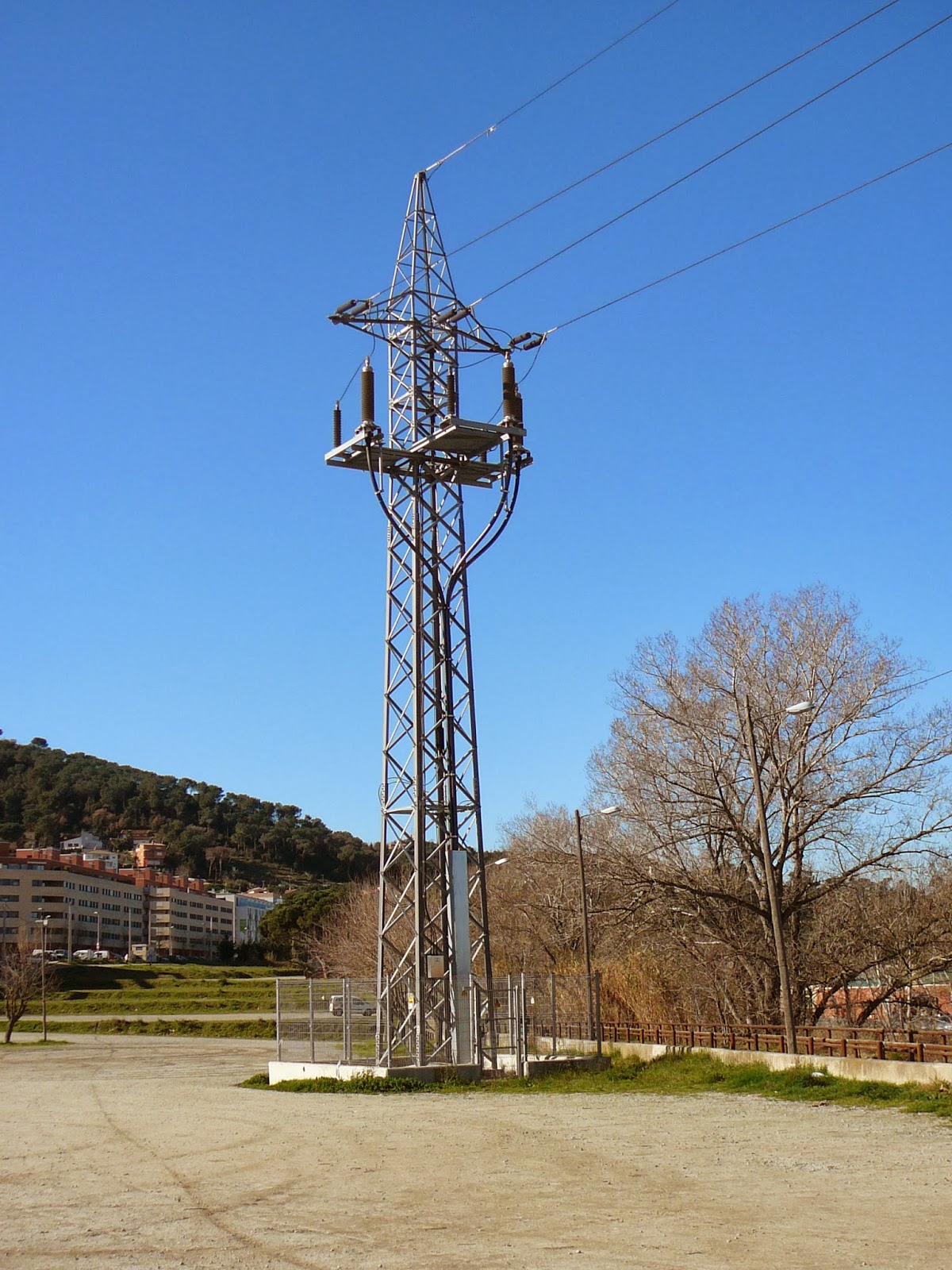
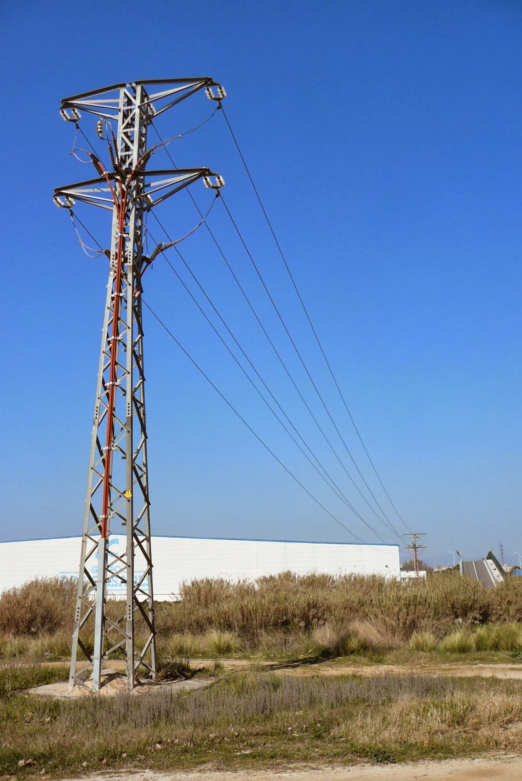
Figure 2_ Example of secondary substation in remote place which uses wireless communication._Source: Javier Sanchez Rios

After the presentation of my project last week about PLC applied to protection systems in small Distributed Generation, I would like to share some examples of possible applications of PLC not getting in deep in the technical features of this promising communication system (which was introduced in previous Part II).

It is possible to think about the control of the urban underground subterranean substation, primary and secondary, where the cost of new infrastructure is very expensive, where the infrastructure can be implemented by PLC, and after being in the ground use wireless communication.
Following with subterranean applications, is possible to think about control (by PWM: Pulse-width Modulation) of the speed and torque from the engine in water pump. Where normally is installed underground, and optimizing the performance from the engine for not working only in ON - OFF and then having a longer life cycle. 
Similarly, it will be possible to transmit information regarding vibration (possible issues in bearings or rotor), electric information, cameras (even thermography), for getting data, and analyze it, for after being able to have properly predictive maintenance. 
At the same time, in the underground infrastructure (sewerage), it is possible to install more sensors for Air quality control, and then, avoiding accidents with professionals who are working in this environment with low levels of oxygen and high level of hydrogen sulphide by the decomposition of organic matter.

In the same way, weather stations and air pollution stations in whatever point in the electric systems will be easy to implement and will give more control of air quality and security in the cities.


Figure 3_ Camera in one central street in Barcelona for controlling traffic._source: Javier Sanchez Rios


3_ It is well known, the Internet by PLC is used, following this application, for home appliances, using Home-plug PLC. Furthermore, PLC can communicate data and to know the possible faults in the appliances by the Vendor, before sending any Technician, and then optimizing Service Performance. 

Similarly, time for using it to update the firmware and software of control boards when new version is released. For implementing this data communication by PLC, it is properly, when there is less interference in LV due to low demand, between 1 and 5 of the night (see Figure 4), to transmit information from the PLC to WANAP (ISP: Internet Service Provider) before or after main interrupter of home electric installation.


Figure 4_ Example of Electric Demand Tracking where is possible to see the low peak demand between 1 and 5 of the night, the proper time to use PLC applications._Source: Ree (Red Eléctrica de España)


Figure 5_ Example of electric and communication system by PLC in the interconnection of EV and Smart Grid by PLC. PLC protocols by Automotive Industry and PLC protocols of Smart Grid._source: Javier Sanchez Rios


Figure 6_ Linux option for developing application for CAN Bus. From terminal instruction; make x config._source: Javier Sanchez Rios


Bibliography:
1_ El Vehículo Eléctrico - Desafíos tecnológicos, infraestructuras y oportunidades de negocio STA: Sociedad de Técnicos de Automoción - Librooks.
2_ Eficiencia en el uso de la Energía Eléctrica - Circutor


Tuesday, March 11, 2014

Power Line Communication - Technical considerations for implementation (Part II)

For implementing PLC, it is necessary to consider next Technical Considerations regarding;
Resource Management and Allocation Techniques:
(1)    Network planning resources, which is related to grid topology;
(2)    PLC resources, which is related to PHYsical (PHY) layer modem parameters
(3)    Traffic resources, which is related to Media Access Control (MAC) layer.

(1) Network Planning

It is necessary to consider the elements in the electric network; taps, branching, splits, bridges, capacitor banks (Reactive Power compensation), recloser, sectionalizers and transformers (implementation of coupling systems) and with Internet Service Provider (ISP), considering at the same time the coexistence with other communication technologies (e.g. , RF, wireless etc).

Bss, as basic element in PLC network, the relays and WANAP's (ISP) must to be quantified properly, PLC modems (or router) are depending of users connected to LV, then it is difficult to be optimized. Then it is necessary to be considered:

(1) Bss (and BM) placement and quantity optimization problem,
(2) relay placement and quantity optimization problem, and
(3) WANAP (Wide Area Network Access Point) choice optimization problem.


Figure 1_ Example of equivalent Electric and PLC scheme of one typical AMI infrastructure. The connection to internet (WANAP) is directly from secondary of the trafo in the secondary substation. Coupling techniques would be installed in Trafos for transmit data from primary to secondary of the trafo or vice versa, depending of the way of communication. Relay is used to switch one station or other station, and one router or routers to other routers (depending of analog or digital meter). Repeater is used to amplify the signal from down link routers, in case of digital meter, mostly are enclosing repeters and of course, router.

(2) PLC Resources
It is possible to define PLC Resource Allocation (PRA) considering Frequency Division Multiple Access (FDMA: channel access method used in multiple-access protocol as a channelization protocol. FDMA gives users an individual allocation of one or several frequency bands or channel, it is used in satellite communication. FDMA, like other Multiple Access systems, coordinates acess between multiple users).

PRA gives great improvements in the system performance with collection of techniques and tools; time-frequency assignment, subcarrier assignment, and power- or bit- rate assignment as function of traffic load, channel condition, channel information availability, and Quality of Service (QoS)  requirements. Considering PHY layer management, by channel profile attenuation, additive noise, and access impedance, are summarized as: 
(1) spectrum allocation and 
(2) power allocation.

(2.1)Spectrum Allocation
OFDM is used by different subsets of the subcarriers for physical layer implementation with frequency diversity and multiuser diversity (when it is possible):
 - Frequency diversity refers to different subcarriers having different channel gains due to the frequency-selective nature of the channel.
- Multiuser diversity refers to different users experiencing different channel conditions due to their distinct locations in the network.
Being necessary to allocate to each user a subset of subcarriers that experience good channel conditions, because one subcarrier may be is good for one user but not for the rest of users.
Spectrum allocation OFDM suggest there types:
(1) OFDM, which determines the set of subcarriers for the user and time slot for the user for down link and up link communications, respectively;
(2) OFDMA, which determines the set of subcarriers allocated to each user for down link and up link communications; and
(3) Clustered-OFDM/OFDMA, which determines the allocations of users in each cluster as well as their set of subcarriers for down link and up link communications.

(2.2) Power Allocation
It is necessary to implement optimum approach  to allocate different power in each subcarrier, being frequency selective in PLC channel, and being classified by three categories: 
 (1) Rate Maximization (RM) issue; using the system bandwidth, BS can transmit with the maximum aggregate data rate to serve PLC modems, considering power limit constraints, knowing the sum-rate capacity maximization.
(2) Margin Adaptive (MA) issue, with minimum QoS requirement for all modems with the lowest possible power.
(3) Rate Adaptive (RA) issue, power allocation in each subcarrier, being total power constant.


(3) Traffic Resources
Cross-layer: PHY and MAC, gives great benefits considering delay and capacity.
The classification of traffic resources allocations and management techniques;
(1) Admission control. If resources are available, the session is admitted. A mechanism to estimate QoS level when new user session is needed having enough resources for this service.
(2) Queue management. Packet classification by placed in queues, identifying and classifying traffic flow.
(3) Traffic scheduling. Traffic flow transmission with necessary QoS parameters which gives the possibility to determine the order users transmissions in terms of slots and subcarriers allowing transmission traffic in time and location.

(3.1) Resource Management and Allocation Techniques
Optimization problems can be solved as Single-Objective Optimization (SOO) problems or as Multi-Objective Optimization (MOO*) problems and may be solved either with exact optimization techniques by heuristic algorithms.

*MOO: is an area of multiple criteria decision making, with mathematical optimization problems involving more than one objective function to be optimized simultaneously, applied in engineering, where optimal decisions need to be taken in the presence of trade-off between two or more conflicting objectives, loosing in one of this objectives in benefit of the opposite.

(3.2) Resource Allocation During Network Planning
The key contributors to implement PLC in terms of resource management and allocation techniques are able to organize in three main categories:
 (1) resource allocation for network planning, which is related to grid topology;
(2) PLC resources based on PHY layer; and
(3) traffic resources, which is related to MAC layer.

(3.3) Analysis of the Transmission Line

Transmission line modeling is one serial circuit with: resistance, capacitance and inductance (R, L , C), determinated by the intrinsic characteristics of the cable: material and geometry. By this parameters, or by experimentally measuring, it is possible to deduce the line's Zc and the propagation constant g.

(3.4) Channel Noise
The noise on the power line communication system is in the 2-30+MHz, being necessary to use mathematical modeling for determining the level of noise. Mostly in LV, the noise has significant impulsive component, limited to frequencies less than 10-20 MHz, with synchronous and asynchronous impulses.
Similarly, aperiodic synchronous and asynchronous impulsive noise is caused by; generatosr and motos synchronized to the power system frequency, power electronic systems by swithching power supplies and automotive spark plugs
On the other hand, high-order harmonics noise of the power line in  2–30+ MHz are able to enter in PLC band (consider harmonics are increasing day by day due to the higher implementation of non linear loads in electronic devices). 
At the same time, especially in MV and HV lines, corona and gap noise must to be considered with background noise. Considering background noise in power line channel, the power spectral density (PSD) is decreasing with the frequency increasing. 
By experimental practices is determined that LV presents low level of noise than MV and HV.
At the same time it is necessary to be considered the change in the characteristics of the noise in the power line due to being or not the power line charged or uncharged.

(3.5) Modulation Schemes
PLC mostly uses Orthogonal Frequency Division Modulation (OFCM), due to the very hostile and time-varying channel, with extensive frequency selectivity to prevent interference to other services.
DS2, Intellon, Amperion and other PLC manufacturers are using OFDM in PLC applications to be compliant to the UPA Digital Home Standards (DHS) specified to Media Access Control (MAC) and PHYsical layers (PHY), based in trellis-coded modulation and TDMA: Time Division Multiple Access which allows several users to share the same frequency channel by dividing the signal into different time slots.


(3.6) Channel Capacity
The level of error-free data rate, by given signal power and channel noise must to be considered for the communication performance.
Of course, higher power offers more capacity, but emissions limits on allowable interference to other users like HAM (Amateur Radio), etc., are able to prevent power from being raised without limit..


(3.7) Power Line Communication Systems
The data in PLC systems are modulated onto a single carrier (*PSK, *QAM, etc) or the multiple carriers of a multi-carrier system (e.g.: OFDM) by coupling systems, in the points of the communication, then coupling systems in the transmitter and the receiver.
Effectively PLC uses In the US and Europe appears with proper power control, notching out of HAM frequencies between 2–34 MHz band (up to even 80 MHz), but final definition is not yet implemented, waiting for PLC more relevance.

*PSK: Phas-Shift Keying: Digital modulation scheme that conveys data by changing, or modulating, the phase of a reference signal (the carrier wave). Any digital modulation scheme uses a finite number of distinct signals to represent digital data. PSK uses a finite number of phases, each assigned a unique pattern of binary digits. Usually, each phase encodes an equal number of bits. Each patterns of bits forms the symbol that is represented by the particular phase.
*QAM: Quadrature amplitude modulation, is both, an analog and digital modulation scheme. It conveys two analog message signals, or two digital bit stream, by changing (modulating) the amplitudes of two carriers waves, using the amplitude-shift keying (ASK) digital modulation scheme or amplitude modulation (AM) analog modulation scheme. The two carriers waves, usually sinusoidal, are out of phase with each other by 90º (quadrature).

(3.7.1) Coupling systems
Coupling systems are essential in PLC systems, for transmitting and receiving data, in a very small communication level signal (1 mW) in a channel with high power (MW). 
This coupling systems are available in inductive or capacitive (in the range of microfarads and microhenry) with isolation transformer and protection systems. In an inductive coupler, a transformer with a capacitive blocker for the power line frequency is used to select the PLC signal from the signal on the line. The couplers can be installed between two phases or between a phase and ground, requiring a minimal conditions of losses at least of 80 dB for the power system frequency, and low of (< 5 dB) of losses in the communication frequency band. 


Ambient Corporation, which provide solutions for Smart Grid Infrastructure, from metering; voltage & current, Partial Discharge monitoring etc, and support PLC applications has a medium voltage coupler power lines up to 25 kV with maximum of 50 kV. The signals can be coupled between the line and ground (neutral), or between two phases in a differential fashion. 
More recent coupling method has lower attenuation, working in high-frequency coupler for the 50–550 MHz band (less than 5 dB loss in a back-to-back connection). 


Figure 2_ Example of Transformer in Distribution Primary Substation, where large component of impulsive noise (overall in LV grid) does not pass through transformer, being coupling techniques the way for achievement the communication


Bibliography: 
1_ Power Line Communication for Smart Grid, Smart Cars, and Smart Homes - Krzysztof Iniewsky and Tracey Mozel.
2_ IEEE 1901.1 - IEEE Standard for Broadband over Power Line Networks: Medium Access Control and Physical Layer Specifications.

Monday, March 10, 2014

Power Line Communication - Protection Systems (Part I)

MV and HV Power Lines incorporates protection systems which takes measurements of information from Power Line. This information is regarding; current, voltage, impedance, frequency etc, with one objective, just for avoiding possible damages in lines (fires, etc) and having in consideration, if the Power System is having more voltage in the Power line, the protection must act quicker.

Normally, for determining, if the line must be disconnected (protection activation), the decision is able to  be taken by one of the points which is monitoring the information (current, voltage, etc), or also, it used to be by "mutual agreement", between the understanding of the two "end points" of the line, where is located the protections systems. This last solution is slower but gives more reliability, understanding that one outage, is able to give serious consequence in the stability of the frequency of the Electric System, with possible cascade reaction for unbalancing in the system by suddenly change in the loads (production/demand).

In case of activation, not necessary being one outage, because the activating of the protection systems is not necessary having one outage, simply by mesh architecture of Electric Networks.
In case of outage managing, the Electric Operators (Distribution or Transmission) uses EMS or DMS systems (Energy or Distribution Management Systems) by WASA (Wide Area Situational Awareness) or ADA (Advanced Distributed Automation; in case of Smart Grid Electric Network).


Figure 1_ Example of possible risk (fire) in whatever situation of non properly functionality of protection systems in the Over Head Power Lines.


The propose of Smart Grid Network is achieved information from sensors installed along the Grid for monitoring faults and predict further outages. PLC (Power Line Communication ) great implemented; AMI (Advance Metering Infrastructure), is able to report information to the Utilities about local outages, when there is no electric consumption in one determined time. All this kind of operations are enclosed in PSSE (Power Systems Simulators for Engineering), examples of those software are: "BigSilent", "PS CAD" or "PSS E"  which give the possibility to simulate protection systems, harmonics, production planning, voltage stability, earth system, contingency analysis etc. 


For having the control between the two points in the power line, this communication is able to be by fiber optic, radio frequency (RF) or PLC (Power line Communication), also called Broadband Power Line.

PLC has been used long time ago (decades), but it has one disadvantage, when there is one fault, the communication channel (Power Line) gets with high noise, and in that case, the communication is critical to assure the protection system. For solving this issues, the PLC needs to work with signals with high robustness and low latency, following the standard IEC 60834-1 (Tele-protection equipment of power systems).

Inside this application explained, the most safe option with great implementation is; "Line differential Protection". This system is working measuring the current waveform in the input of the line and this measurement is compared with the current waveform of the output of the line. For that, both waves must to be equal sample by sample (Nyquist Theorem: sample limited in band range and sampling process higher than double of Bandwidth). If there is no this condition, the system understands there is a short in this delimited line.

One issue presented in the waveform sample by sample compared is the propagation delay, being this waveform as sinusoidal. For solving this propagation delay, the system uses time slogans coming from GPS (Global Positioning System).

The maximum allowable time error depends of voltage level in the Power Line. The solution implemented nowadays is one system which monitor the phasors (PMU: Phasor Monitoring Unit), using synchrophasors. Being this application optimal for controlling the Protection of Distribution and Transmission Lines in a wide area of Smart Grid infrastructure: WASA (Wide Area Situational Awareness).

In HV Power Lines, this time of reaction is related 150 µs. In concrete, for PLC communications, when there is one fault and/or short, the noise and/or distortion are getting higher.
In this situation, PLC application implemented for a big range of protection (distance) is able to lose the synchronization and to spend more time than 150  µs in recovering the state.
In this situation, when the system needs the most proper reliability in the complete system of: differential protection + PLC, this systems is not working properly.
For that reason, PLC for differential protection is not used, and is used by Fiber Optic systems integrated in the cable lines (OPGW: Optical Power Ground Wire).

In MV, the time for disconnecting are lower, being 200 or 300 ms, and having the same issue than in HV Power lines, not being properly solution (PLC) for big range of protection area (distance).


When the protection systems are monitoring currents and voltages (over current and over voltage protections) used to work such as isolated system, with no issues regarding noise or other disturbance. In this case, the system is able to work jointly by systems designed properly for that application, specially for non loosing the synchronization, even in outages. This systems are called Tele-protection.


Figure 2_ Examples of Power Line: from subterranean to Overhead Power Line for crossing a river. Where there is the possibility for PLC is able to establish the communication in this subterranean line and after change to the wireless system or Fiber Optic in the OH Power Line.