MV and HV Power Lines incorporates protection systems which takes measurements of information from Power Line. This information is regarding; current, voltage, impedance,
frequency etc, with one objective, just for avoiding possible damages in lines
(fires, etc) and having in consideration, if the
Power System is having more voltage in the Power line, the protection must act
quicker.
Normally, for determining, if the line must be
disconnected (protection activation), the decision is able to be taken by one of the
points which is monitoring the information (current, voltage, etc), or also, it
used to be by "mutual agreement", between the understanding of the two
"end points" of the line, where is located the protections systems.
This last solution is slower but gives more reliability, understanding that one
outage, is able to give serious consequence in the stability of the frequency
of the Electric System, with possible cascade reaction for unbalancing in the
system by suddenly change in the loads (production/demand).
In case of activation, not necessary being one outage,
because the activating of the protection systems is not necessary having one
outage, simply by mesh architecture of Electric Networks.
In case of outage managing, the Electric Operators
(Distribution or Transmission) uses EMS or DMS systems (Energy or Distribution
Management Systems) by WASA (Wide Area Situational Awareness) or ADA (Advanced
Distributed Automation; in case of Smart Grid Electric Network).

Figure 1_ Example of possible risk (fire) in whatever situation of non properly functionality of protection systems in the Over Head Power Lines.
The propose of Smart Grid Network is achieved
information from sensors installed along the Grid for monitoring faults and
predict further outages. PLC (Power Line Communication ) great implemented; AMI (Advance Metering Infrastructure), is able to
report information to the Utilities about local outages, when there is no
electric consumption in one determined time. All this kind of operations are
enclosed in PSSE (Power Systems Simulators for Engineering), examples of
those software are: "BigSilent", "PS CAD" or "PSS E" which give the possibility to
simulate protection systems, harmonics, production planning, voltage stability,
earth system, contingency analysis etc.
For having the control between the two points in the
power line, this communication is able to be by fiber optic, radio frequency
(RF) or PLC (Power line Communication), also called Broadband Power Line.
PLC has been used long time ago (decades), but it has
one disadvantage, when there is one fault, the communication channel (Power
Line) gets with high noise, and in that case, the communication is critical to
assure the protection system. For solving this issues, the PLC needs to work
with signals with high robustness and low latency, following the standard IEC
60834-1 (Tele-protection equipment of power systems).
Inside this application explained, the most safe
option with great implementation is; "Line differential Protection".
This system is working measuring the current waveform in the input of the line
and this measurement is compared with the current waveform of the output of the
line. For that, both waves must to be equal sample by sample (Nyquist Theorem:
sample limited in band range and sampling process higher than double of
Bandwidth). If there is no this condition, the system understands there is a
short in this delimited line.
One issue presented in the waveform sample by sample
compared is the propagation delay, being this waveform as sinusoidal. For
solving this propagation delay, the system uses time slogans coming from GPS
(Global Positioning System).
The maximum allowable time error depends of voltage
level in the Power Line. The solution implemented nowadays is one system which
monitor the phasors (PMU: Phasor Monitoring Unit), using synchrophasors. Being
this application optimal for controlling the Protection of Distribution and
Transmission Lines in a wide area of Smart Grid infrastructure: WASA (Wide Area
Situational Awareness).
In HV Power Lines, this time of reaction is related
150 µs. In concrete, for PLC communications, when there is one fault and/or
short, the noise and/or distortion are getting higher.
In this situation, PLC application implemented for a
big range of protection (distance) is able to lose the synchronization and to
spend more time than 150 µs in recovering the state.
In this situation, when the system needs the most
proper reliability in the complete system of: differential protection + PLC,
this systems is not working properly.
For that reason, PLC for differential protection is
not used, and is used by Fiber Optic systems integrated in the cable lines
(OPGW: Optical Power Ground Wire).
In MV, the time for disconnecting are lower, being 200
or 300 ms, and having the same issue than in HV Power lines, not being properly
solution (PLC) for big range of protection area (distance).
When the protection systems are monitoring currents
and voltages (over current and over voltage protections) used to work such as
isolated system, with no issues regarding noise or other disturbance. In this
case, the system is able to work jointly by systems designed properly for that
application, specially for non loosing the synchronization, even in outages.
This systems are called Tele-protection.
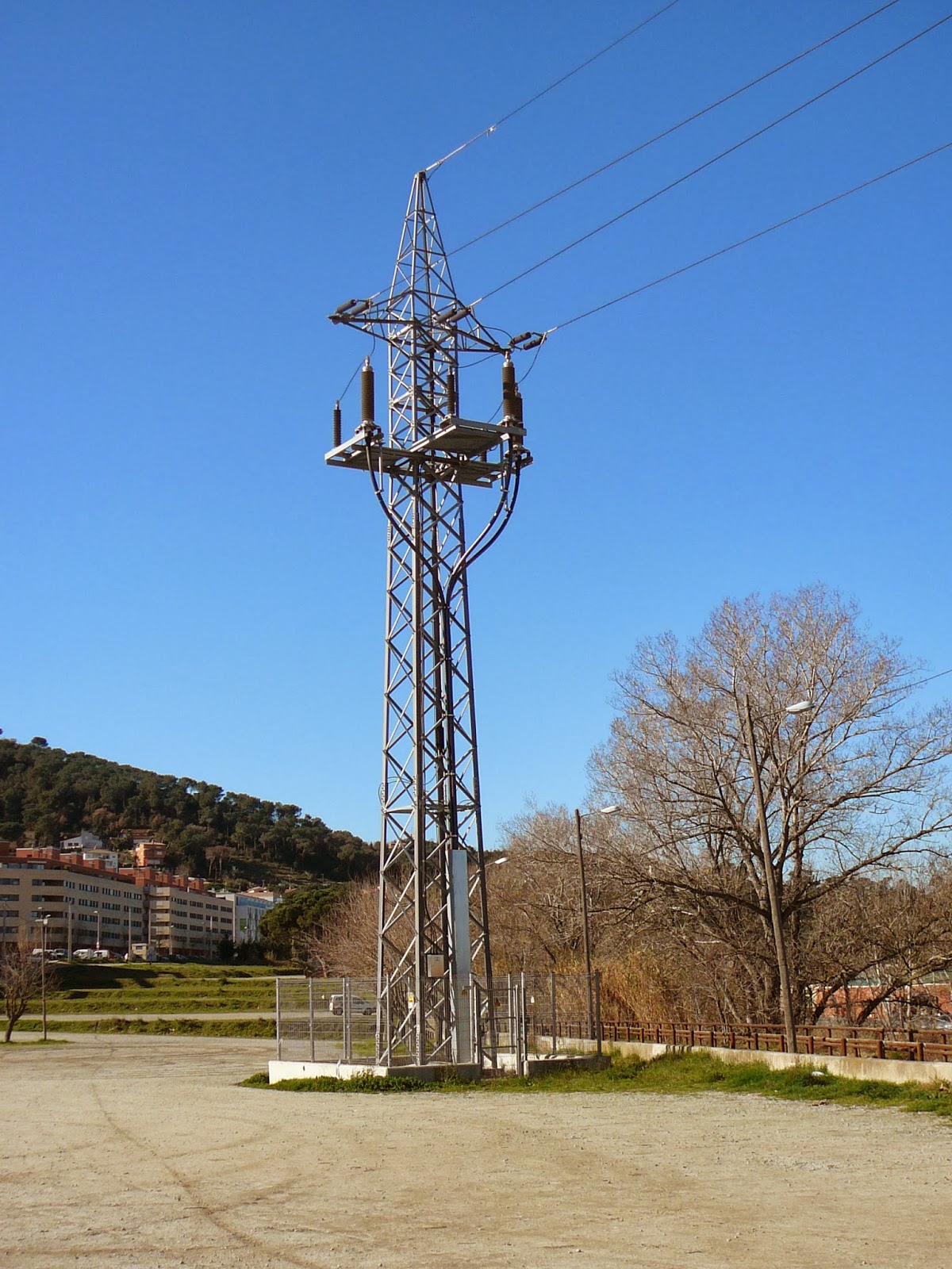
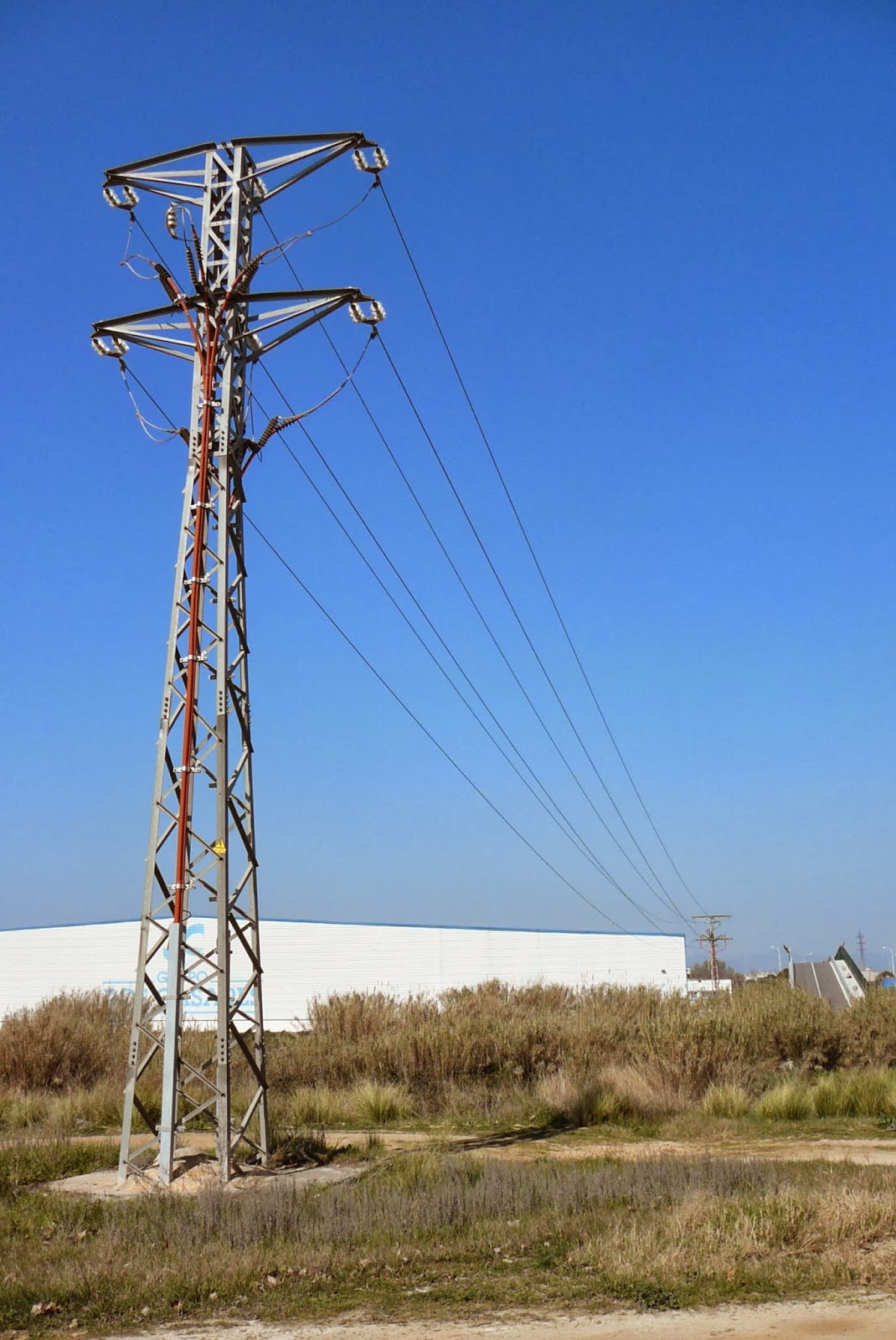
Figure 2_ Examples of Power Line: from subterranean to Overhead Power Line for crossing a river. Where there is the possibility for PLC is able to establish the communication in this subterranean line and after change to the wireless system or Fiber Optic in the OH Power Line.
No comments:
Post a Comment